|
|
|||||||||
| Software: RF Cascade Workbook | RF Symbols for Office | RF Symbols & Stencils for Visio | Espresso Workbook | ||||||||||
|
|||||||||||||||||||||||||||||||
  |
  |
||||||||||||||||||||||||||||||
|
Please Support RF Cafe by purchasing my ridiculously low-priced products, all of which I created. RF & Electronics Symbols for Visio RF & Electronics Symbols for Office RF & Electronics Stencils for Visio T-Shirts, Mugs, Cups, Ball Caps, Mouse Pads These Are Available for Free |
|||||||||||||||||||||||||||||||


Esser Tools 8000 User Manual Pdf 2021
Esser Tools 8000 User Manual Pdf 2021
Esser Tools 8000 User Manual Pdf 2021
: Allows for automatic identification of bus devices, allocation of detector groups, and setting time delays or timer controls. Loop Diagnosis
Visualizes networked fire alarm control panels and identified terminals. : Diagnoses cable disconnections or short circuits. Esser Tools 8000 User Manual Pdf
A complete, authentic Esser Tools 8000 manual is structured into the following chapters: : Allows for automatic identification of bus devices,
The Esser Tools 8000 is a multi-functional device designed to perform various tasks, including testing, measurement, and analysis. Its advanced features and capabilities make it an essential tool for professionals in the field. The device is equipped with a user-friendly interface, allowing users to easily navigate and operate the device. A complete, authentic Esser Tools 8000 manual is
: It is downward compatible with older panels like the FACP 8007 and 8008, and runs on Windows 7 or higher (with older versions supporting Windows 98). Documentation Resources
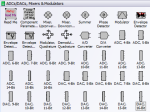
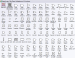
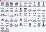
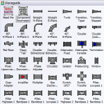
 This set of more than 1,000 uniquely
designed RF & Electronics Stencils for Visio™
were built in Visio™ 2007 and tested in 2019. They use the .vss and .vsd
file formats, which is compatible with Visio™ 2003 up through the most
current version.
This set of more than 1,000 uniquely
designed RF & Electronics Stencils for Visio™
were built in Visio™ 2007 and tested in 2019. They use the .vss and .vsd
file formats, which is compatible with Visio™ 2003 up through the most
current version.
Every stencil symbol has been built to fit proportionally on the included A-, B-, and C-size drawing page templates (or use your own page if preferred). Components are provided for system block diagrams, conceptual drawings, schematics, test equipment, racks (EIA 19", ETSI 21"), and more.
Test equipment and racks are built at a 1:1 scale so that measurements can be made directly using Visio built-in dimensioning objects. Page templates are provided with a preset scale (changeable) for a good presentation that can incorporate all provided symbols. A look through the stencil sets below testifies to the claim of completeness, and a consistent appearance will assure a premium quality presentation. These symbols took many hundreds of hours to create, so the minimal cost can easily be justified for time they will save you.
Below are screen captures of all the stencil sets provided with RF & Electronics Schematic & Block Diagram Stencils for Visio™ (r4). Click on the thumbnails for large versions. Please check the NOTES section on this page for instructions and/or any updates.
| AC, DC, Signal Sources
|
 |
| Amplifiers, Opamps
|
 |
| Antennas, Towers
|
 |
| ARRL 2011 Handbook Symbols |
 |
| Attenuators, Terminations
|
 |
| Connectors
Special "Connector Kit" makes building in-series and between-series adapters simple. |
 |
| Converters, Mixers, Modulators, Detectors
|
 |
| Couplers, Hybrids, Samplers
|
 |
| Digital, Logic
|
 |
| EIA 19" Equipment Racks
Special "Workbench Kit" makes building a workbench of any size easy. |
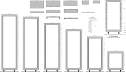 |
| ETSI (metric) 21" Equipment Racks
|
 |
| Filters, Diplexers, Duplexers
|
 |
| Planes, Trains, and Automobiles, Wireless Devices
|
 |
| Panel Components
|
 |
| Resistors, Capacitors, Inductors, Transformers, Lamps, Passives
|
 |
| Semiconductors
|
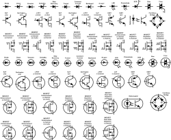 |
| Substrate Stacks
|
 |
| Switches
|
 |
| Test Equipment
Flanges for rack mounting and frames for bench top placements included. Instruments are generic and can be modified as needed. |
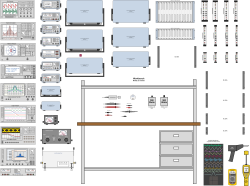 |
| Vacuum Tubes
|
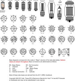 |
| Waveguide
|
 |
| Component Parameters
|
 |
|
Page Template, Size A Landscape
Page Template, Size B Portrait
Page Template, Size C Landscape
Smith Chart™ Smith Chart rights owned by the IEEE |
Page Template, Size A Portrait
Page Template, Size B Landscape
Page Template, Size C Portrait |


Copyright: 1996 - 2026 |
About RF Cafe RF Cafe began life in 1996 as "RF Tools" in an AOL screen name web space totaling 2 MB. Its primary purpose was to provide me with ready access to commonly needed formulas and reference material while performing my work as an RF system and circuit design engineer. The World Wide Web (Internet) was largely an unknown entity at the time and bandwidth was a scarce commodity. Dial-up modems blazed along at 14.4 kbps while tying up your telephone line, and a lady's voice announced "You've Got Mail" when a new message arrived... |
Copyright 1996 - 2026 All trademarks, copyrights, patents, and other rights of ownership to images
and text used on the RF Cafe website are hereby acknowledge My Hobby Website: My Daughter's Website: |
